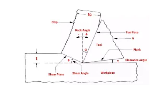
In this article, we will learn what is chip thickness ratio, how to derive it, how to calculate it with a formula as well as will learn on the relation between chip thickness ratio, shear angle, and rack angle.
What is Chip Thickness Ratio?
The chip thickness ratio represents the proportion of metal thickness before cutting to the thickness after cutting. In the cutting process, the tool’s cutting edge is situated at a specific distance below the original metal surface, corresponding to the initial chip thickness. As the chip forms along the shear plane, its thickness undergoes an increase, denoted as tc (After cutting chip thickness).
Read also: Try Square: Parts, Types, Grades, Checking Accuracy, Uses
So the ratio t/tc is called the chip thickness ratio.
It is represented by r.
So,
r = t/tc
Where,
t = uncut chip thickness
tc= cut chip thickness
Derivation of Chip Thickness Ratio
The chip thickness ratio can be derived from the volume of the chip.
Let assume,
l = length of the chip before cutting
b = width of the chip before cutting
t = thickness of chip before cutting
lc = length of the chip after cutting
bc = width of chip after cutting
tc = thickness of chip after cutting
As we know,
The volume of the chip before cutting is equal to the volume of the chip after cutting.
So,
l × b × t = lb × bc × tc
Generally, the width of the chip is to be taken as negligible.
So,
b = bc
Then,
l × t = lb × tc
t/tc = lb/l
So,
Chip thickness ratio,
r = t/tc = lb/l
Chip Reduction Ratio or Coefficient
Defined as the ratio of chip thickness after cutting to the chip thickness before cutting, the chip reduction ratio or coefficient, denoted as E, exhibits an inverse relationship with the chip thickness ratio. The upcoming exploration will uncover the relationship between chip thickness ratio, shear angle, and rack angle, preceded by an understanding of shear and rack angles.
Read also: Are PET Bottles Safe for us and the environment?
What is Shear Plane Angle?
Shear stress occurs as the metal at the forefront of the tool undergoes compression, reaching its maximum along a designated plane known as the shear plane. The angle formed by the shear plane with the tool’s direction of movement is referred to as the shear plane angle.
It is denoted by ɸ.
The chip flow velocity is affected by the shear plane angle.
What is Rack Angle?
It is the angle between the rack face and normal to the machine direction.
It is denoted by α.
Relation Between Chip Thickness Ratio, Shear Angle and Rack Angle
See in the figure chip produced during the machining process.
Where,
ɸ = Shear Angle
α = Rack Angle
t = uncut chip thickness
tc= cut chip thickness
Now if we make separate angle then,
See in triangle ABC,
As we know that,
Sinɸ = Perpendicular/Hypotenuse
So,
Sinɸ = t/AB
t = AB×Sinɸ
Now, See in triangle ABD,
As we know that the sum of the total triangle angle is equal to 180°.
Hence,
x + 90 + (90 – ɸ) + α = 180°
x = 180 – 90 – (90 – ɸ) – α
x = ɸ – α
So as we know,
Cos(ɸ – α) = Base/Hypotenuse
Cos(ɸ – α) = tc/AB
tc = AB × Cos(ɸ – α)
So, as we know that,
r = t/tc
r = AB×Sinɸ/AB × Cos(ɸ – α)
r = Sinɸ/Cos(ɸ – α)
r = 1/E
Where,
E = Chip reduction ratio or coefficient
So,
As we know the chip thickness ratio,
r = Sinɸ/Cos(ɸ – α)
Then
r × Cos(ɸ – α)= Sinɸ
Now open Cos(ɸ – α) by Trigonometry formula then,
r × ( cosɸ × cosα + sinɸ × sinα) = sinɸ
r × cosɸ × cosα = (1 – r × sinα)sinɸ
cosɸ/sinɸ = (1 – r × sinα)/r cosα
tanɸ = r × cosα/ (1 – r × sinα)
Calculation of Chip Thickness Ratio and Shear Angle
Question
In an orthogonal cutting machining operation with a cutting tool rack angle of 10°, the initial chip thickness is 0.50 mm, and post-cutting, it becomes 1.125 mm. Determine the chip thickness ratio and shear plane angle.
Solution
Given Data,
α = 10°
t = 0.50mm
tc = 1.125mm
As we know that,
Chip thickness ratio,
r = t/tc
r = 0.50 / 1.125
= 0.44mm
So chip thickness ratio will be 0.44mm.
Now,
As we know,
tanɸ = r × cosα/ (1 – r × sinα)
tanɸ = 0.44 × cos10/(1-0.44 × sin10)
tanɸ = 0.4691
Hence,
Shear Ange,
ɸ = 25.13°
That concludes the article, and I appreciate your time reading it. Feel free to drop any questions about “chip thickness ratio” in the comments section. If you find the information on “chip thickness ratio” valuable, consider sharing it with your friends.
FAQ Related to Chip Thickness Ratio
What is the reason for the chip thickness ratio consistently being less than 1?
The chip thickness after cutting consistently surpasses the thickness before cutting, resulting in a chip ratio that is always less than 1.
Is the chip reduction coefficient invariably greater than 1?
Yes, because the chip reduction coefficient is inversely proportional to the chip thickness ratio, and since the chip thickness ratio is always less than 1, the chip reduction coefficient is always greater than 1.
What significance does the chip thickness ratio hold?
The chip thickness ratio serves as a crucial parameter in machining analysis, offering insights into the deformation of the chip across its thickness.
Related

